
| Version 10 (modified by , 20 years ago) ( diff ) |
|---|
FEB proto 3 : Synchronization
TracNav
- Front-End Board
- Status of the Electronics at the Pit
- CROC
- Backplane
- Radiation Tolerance
- Documents
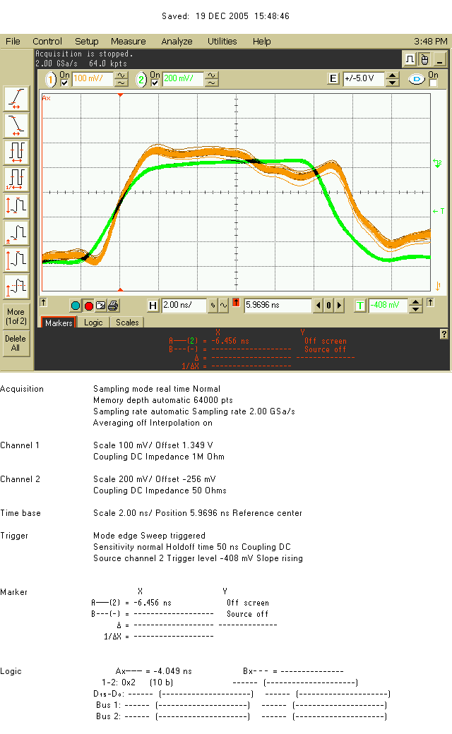
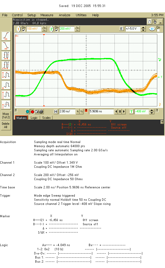
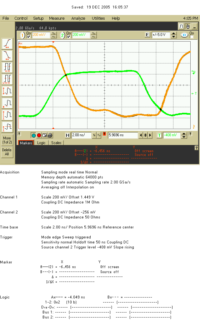
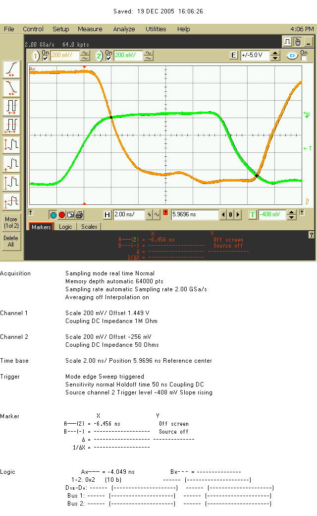
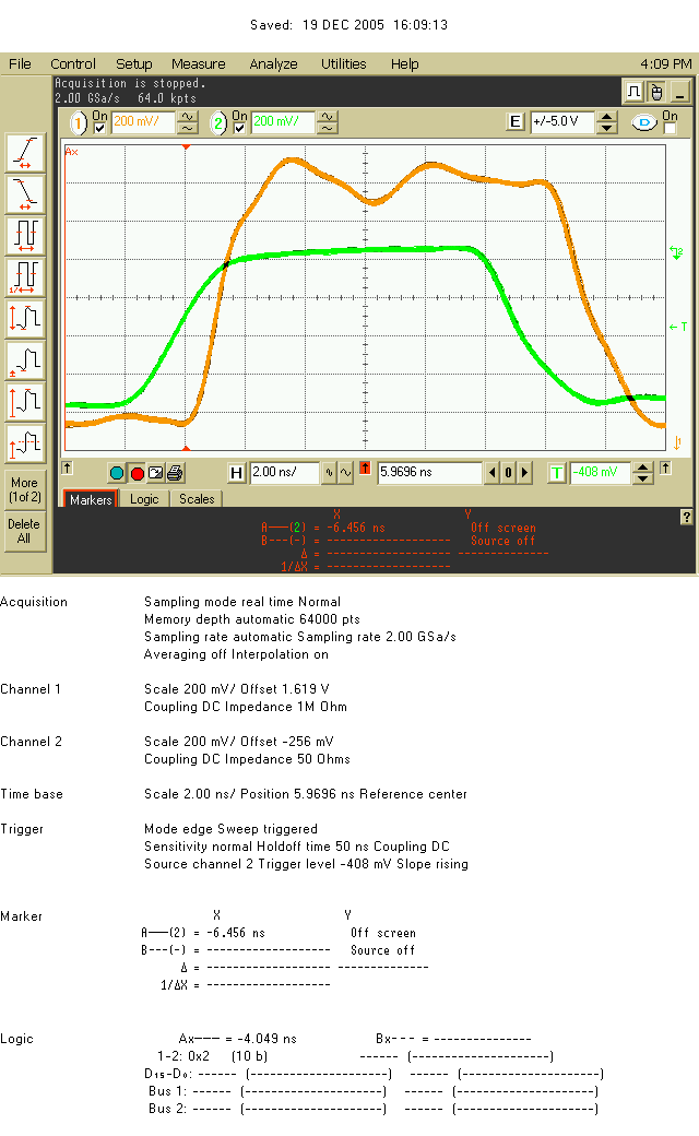
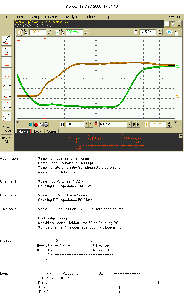
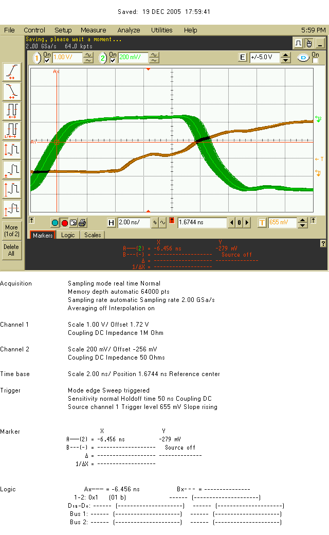
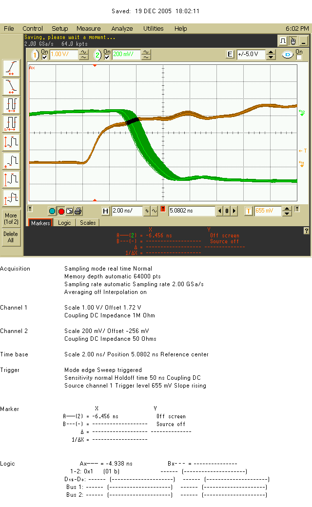
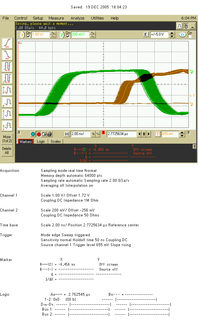
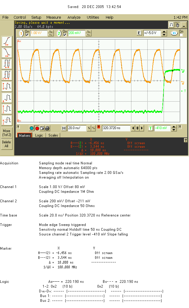
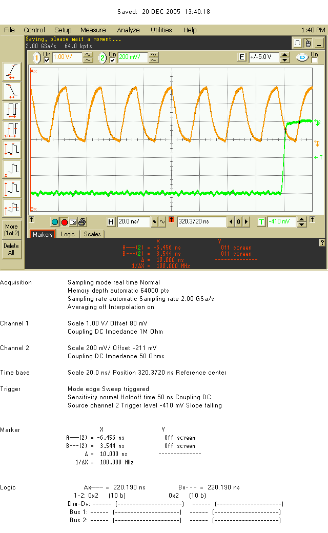
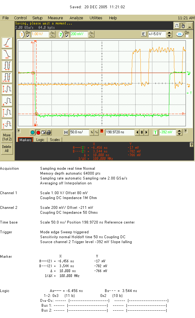
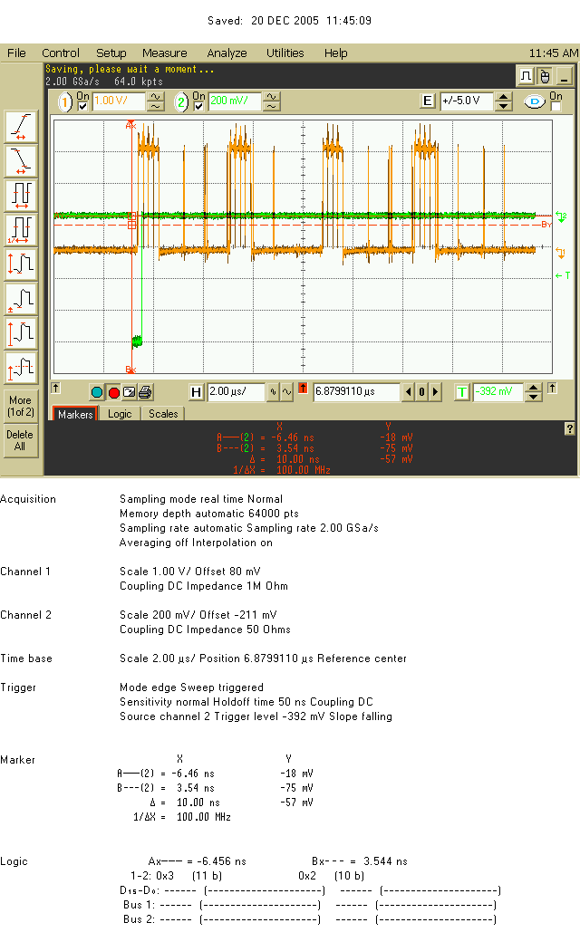
In the following, the green signal is the reference CROC Global clock signal (CROC quartz), the yellow signal is either the clock of the front-end board, the L0 or the read_command. Green is the trigger for the clock study, the yellow signal is the trigger when looking at the L0 and the Read Command. The time scale is 2ns.
Djitter Clock
Incoming clock signal taken at the input of the LVDS/unipolar convertor of the board (polarity minus)

Clock signal taken at the output of the clock buffer driver.

Clock signal taken at the output of the Delay chip for ADC 0.

Clock ADC 0 (polarity +).

Clock ADC 0 (polarity -).

Djitter L0
L0 signal at the output of the LVDS/unipolar convertor of the FEB.

L0 signal at the output of the Sequencer : a large (~1ns) djitter appears.

Djitter Read Command
First RdCmd at the output of the Sequencer. The First RdCmd is used as the scope trigger. Large djitter wrt to the CROC clock.

One of the next RdCmd (8?). We have both a djitter wrt the clock (green) but also wrt the first RdCmd still used as the trigger reference. Rd_Cmd have djitters amongs themselves -> no sampling at the output of the sequencer ?

Attachments (15)
- clock2.bmp (100.7 KB ) - added by 20 years ago.
- clock3.bmp (98.8 KB ) - added by 20 years ago.
- clock4.bmp (99.7 KB ) - added by 20 years ago.
- clock5.bmp (99.1 KB ) - added by 20 years ago.
- clock6.bmp (100.0 KB ) - added by 20 years ago.
- L0_1.bmp (95.8 KB ) - added by 20 years ago.
- L0_2.bmp (97.2 KB ) - added by 20 years ago.
- rd_1.bmp (95.5 KB ) - added by 20 years ago.
- rd_2.bmp (97.8 KB ) - added by 20 years ago.
- Delay_Chip_Output18.bmp (110.2 KB ) - added by 20 years ago.
- Delay_Chip_Output20.bmp (110.1 KB ) - added by 20 years ago.
- Delay_Chip_Output22.bmp (109.5 KB ) - added by 20 years ago.
- Delay_Chip_Output24.bmp (108.6 KB ) - added by 20 years ago.
- L0data1.bmp (107.8 KB ) - added by 20 years ago.
- L0data2.bmp (121.7 KB ) - added by 20 years ago.
Download all attachments as: .zip